Most rotating equipment contains bearings. Electric motors, pumps, and industrial fans are some examples of equipment that include bearings among their components.
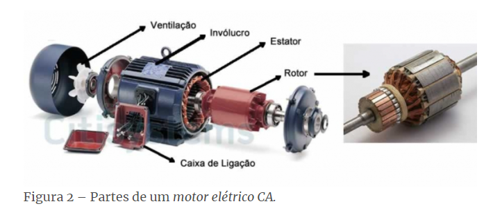
There are various types of bearings on the market (e.g., ball bearings, roller bearings), but they are similar in their main components:
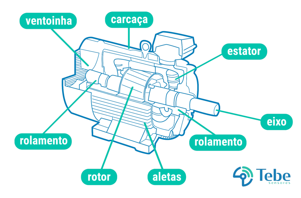
The sensors should be installed in rigid areas, preferably near the motor bearings, to detect failures in these components. The installation locations are highlighted below:
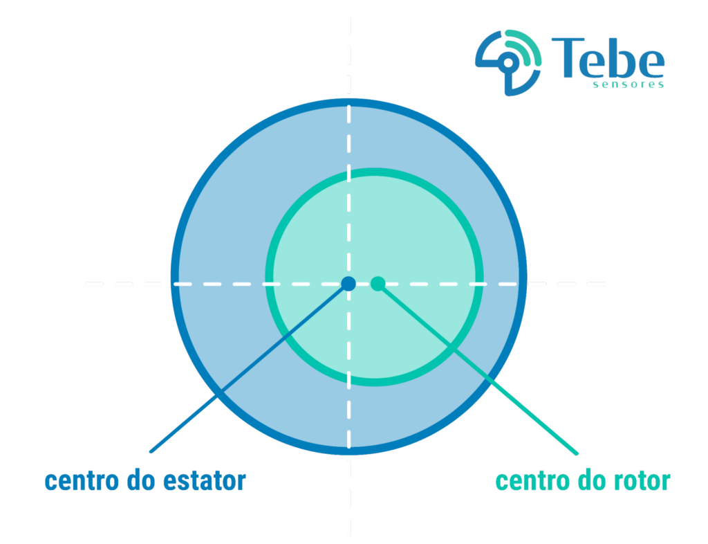
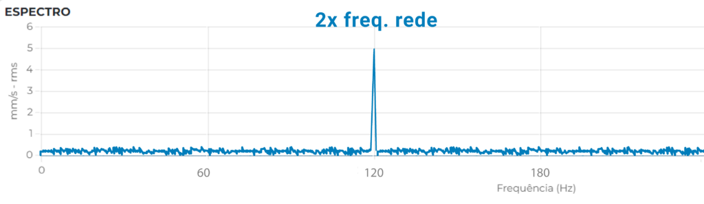
Static eccentricity refers to eccentricity that does not move, for example, due to bearing wear, a deformed stator, or clearance between the bearing cover and the outer raceway.
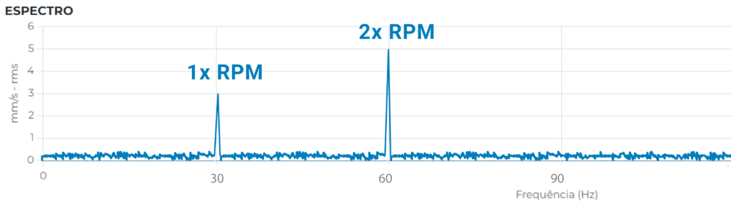
Under these conditions, the spectrum will be centered at twice the mains frequency (60 Hz in Brazil), and therefore the spectrum will be of the type:
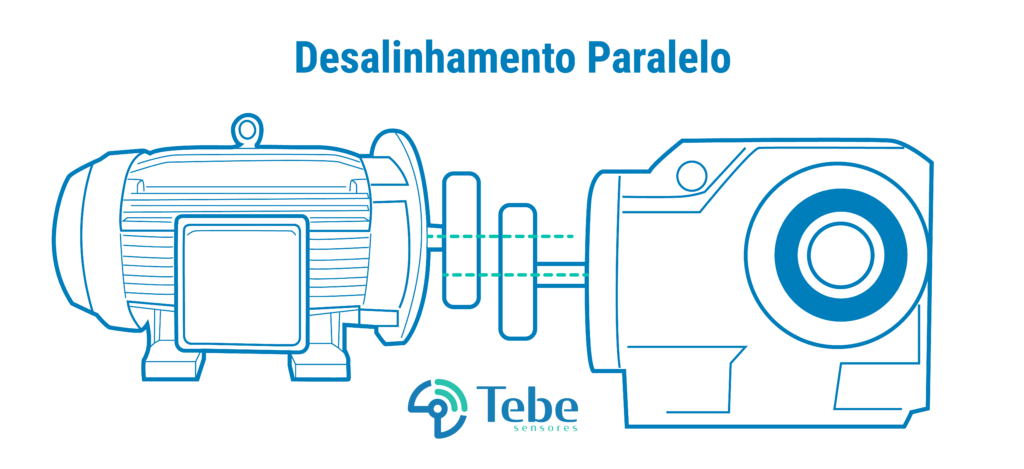
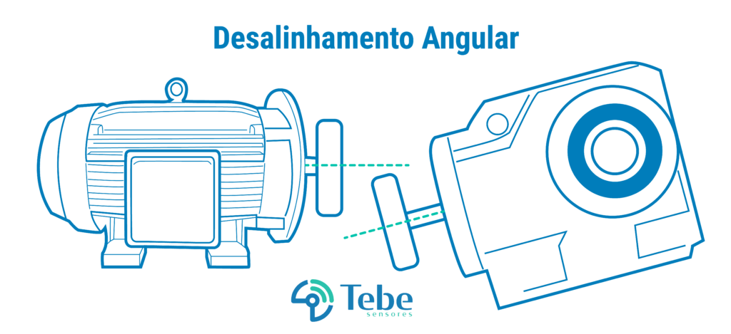
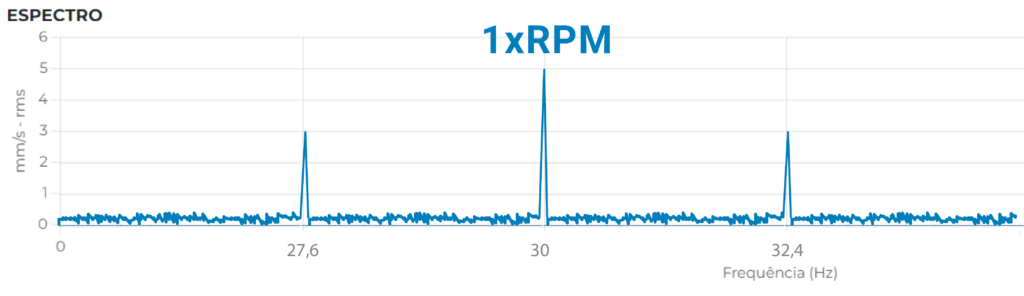
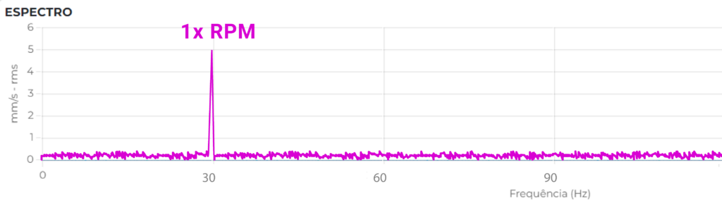
This occurs due to misalignment between the electric motor and the connected machine. It can be diagnosed by analyzing the speed spectrum, where the 1x frequency in the axial direction and/or the 2x frequency in the radial direction are highlighted.
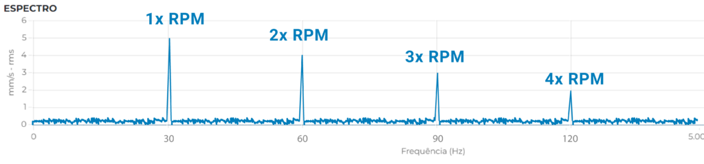
Gaps may occur due to loose screws on the motor base, or even in cases where the base is not rigid (e.g., a motor mounted on sheet metal structures, etc.). These characteristics cause the spectrum to exhibit many harmonics, as shown in the image below:
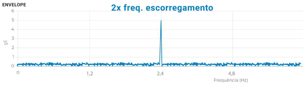
This failure is critical to ensuring the company's reliability, as bearings are key components in the industry.
Basically, bearing failures are diagnosed at an early stage using the envelope technique, which highlights the failure frequencies of the bearings.