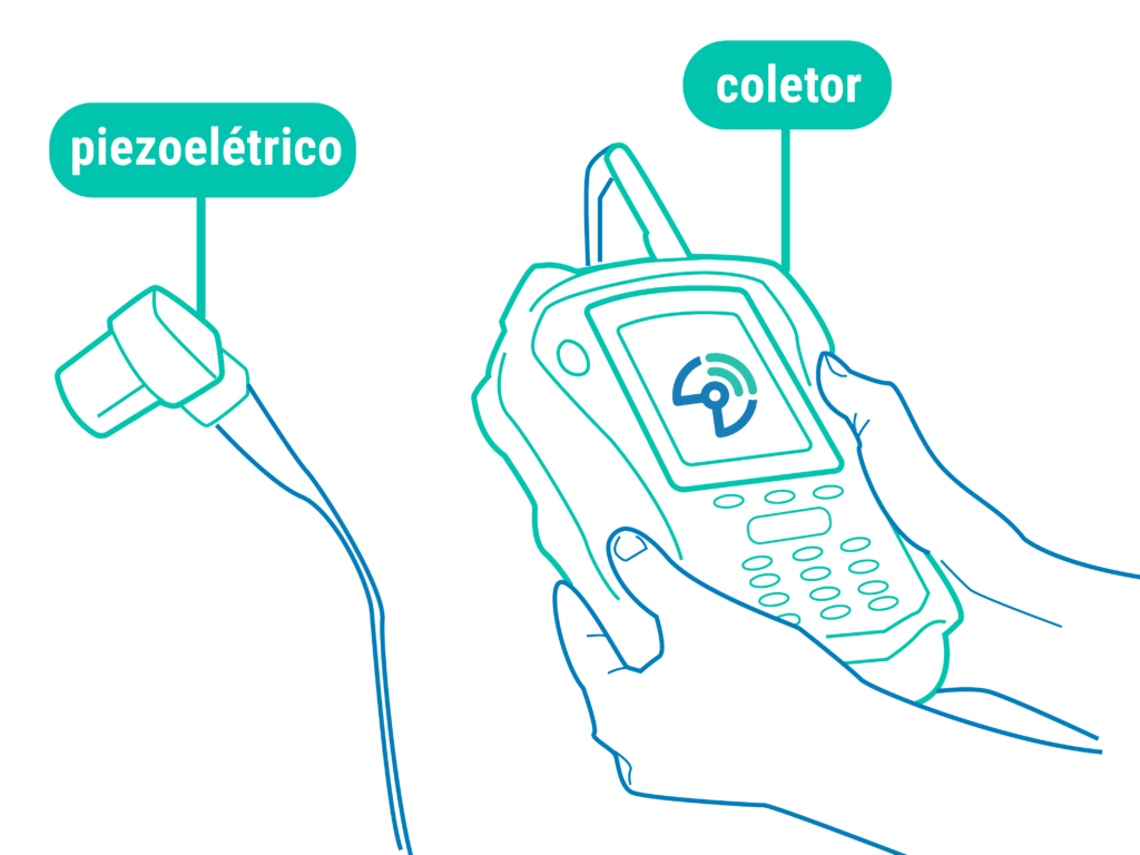
Piezoelectric accelerometers are the most widely used sensors in the field of vibration. Many analysts have been using them for years, as these devices offer high precision and data reliability. It is common to use these sensors in conventional vibration transducers, as shown in the illustration below:
Industry 4.0 has been characterized by the introduction of battery-powered sensors that can last for years without the need to invest in cabling, power, and other infrastructure requirements that previously made it impractical to install sensors on many pieces of equipment.
For this to be possible, there has been significant progress in the development of electronic circuits capable of delivering high precision while consuming little power.
The vibration and temperature sensor Tebe NXG offers all the benefits mentioned above:
- Accuracy in vibration and temperature measurement;
- High-frequency range, capable of detecting bearing failures at an early stage;
- Low power consumption (2.5-year battery life);
- Durability (withstands exposure to damp environments and water jets).
But is Tebe NXG really reliable?
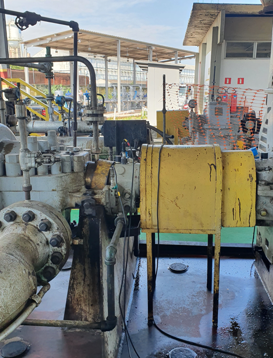
To answer this question, this article presents a real-world case study comparing our sensor—installed in the bearing of a centrifugal pump—with a piezoelectric accelerometer.
We conducted the test to study the machine’s vibrational behavior and to validate the NXG’s measurements in the field. We installed the two sensors on the pump bearing and concluded that THE TEBE NXG COLLECTS INCORRECT VIBRATION READINGS. Yes, our sensor showed velocity values (mm/s) much higher than those of the piezo, and that was exactly what we wanted. Why?
But why?
This is because the measurements were taken at different points on the machine, as indicated in the image below. The Tebe was mounted on the top of the pump (Point 01) and the piezoelectric sensor on the equipment’s axis line (Point 02). To test this hypothesis, we monitored both points on the pump again, using a Tebe NXG and a piezoelectric sensor at each location.
The measurements were taken with the machine operating at its rated speed under standard industrial conditions. We noted that, at point 02, the Tebe sensor showed similar speed values on the vertical and horizontal axes, and a slightly lower value on the axial axis. The same behavior was observed in the piezoelectric sensor readings. At point 01, however, the vertical and horizontal axes again showed similar values, while the axial axis exhibited a value significantly higher than the former two, a situation also observed with the piezo.
But it doesn't stop there. We wanted to push the Tebe to its limits by putting it through every test at our disposal.
The final test
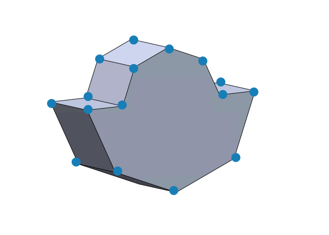
In order to investigate the machine's condition in greater detail, we applied the ODS technique ( Operating Deflection Shape ) technique. To do this, we measured strategic points on the pump bearing and created a 3D computational model of it:
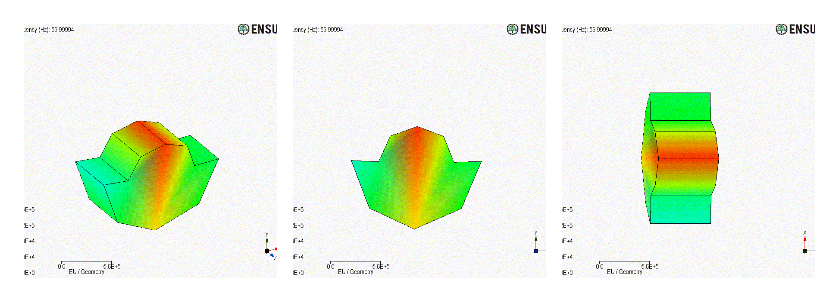
So, we entered the vibration data collected at these points into the simulation, which resulted in the videos below:
We therefore observed that the top of the bearing exhibited a much greater amplitude than the rest of the structure, as evidenced by the movement and the reddish colors shown in the animation. In other words, the Tebe NXG was NOT measuring incorrect vibration values: it was, in fact, demonstrating the variation in vibration occurring at different points on the analyzed bearing. Since the bearing was experiencing a much greater amplitude at the top, corresponding to the axial axis at Point 01, the sensors naturally collect higher data values when installed in this region.
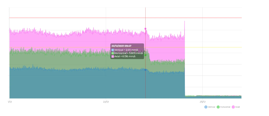
Notice how, in the speed graph recorded on IoTebe , this behavior is confirmed: the values on the axial axis at Point 01, shown in pink, are much higher than those on the vertical and horizontal axes (shown in blue and green, respectively).
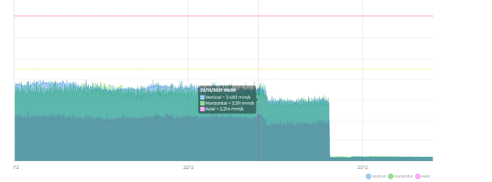
At Point 02, the vertical and horizontal axes have similar values, while the axial value is lower:
The reliability of the Tebe sensor was thus demonstrated both in comparison with the well-established piezoelectric sensor and through analysis of the machine’s simulated behavior in ODS.
Where is the correct location for installing the Tebe NXG?
Vibration analysis relies heavily on the equipment's history, and from that perspective, the sensor could be installed at both locations. If the machine's condition deteriorates, vibrations will increase at both Point 01 and Point 02.
If alerts (warning and critical) are defined according to pre-established standards, it is important to take the installation location into account when setting the machine’s operating threshold based on the levels specified in the standard.
Why invest in Industry 4.0?
You might be wondering, “If the results were the same, why should I invest in the Tebe NXG if I already have a piezoelectric sensor?” The answer is simple: real-time monitoring . The piezo operates on a periodic inspection schedule, while Tebe monitors the machine’s health 24 hours a day. The smart sensor captures an incomparably larger amount of data, which is crucial for early fault detection.
Early detection of these faults ensures reduction in repair costs , as well as preventing unscheduled production downtime and the resulting loss of revenue.